订阅话题
一、实验目的
学习STM32-microROS组件,接入ROS2环境,订阅int32话题。
二、硬件连接
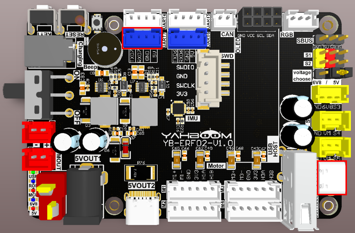
如下图所示,STM32控制板集成了STM32H743芯片,可使用microros框架程序。
请把type-C数据线连接主控板USB口和STM32控制板的USB Connect接口。
如果有CH340等USB转串口模块,可连接串口助手查看调试信息。
由于ROS2需要用到Ubuntu环境,建议主控板安装Ubuntu22.04和ROS2环境。
注意:主控板类型比较多,这里以Jetson Orin系列主控板,默认烧录出厂镜像的情况为例。
三、核心代码解析
程序源码对应的虚拟机路径为:
Board_Samples/Microros_Samples/Subscriber
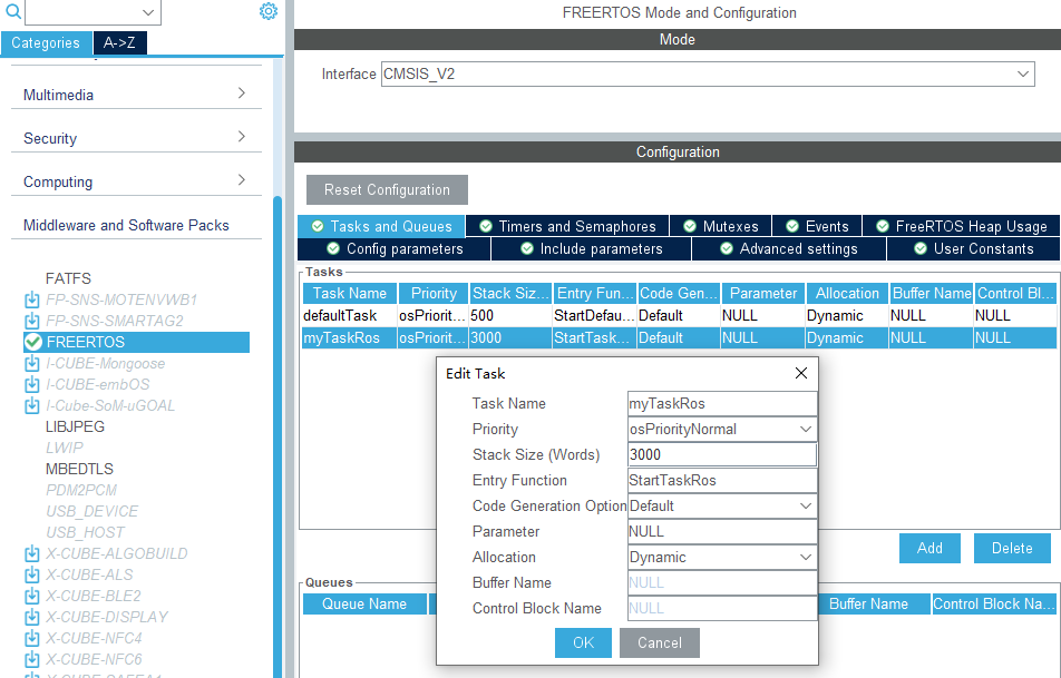
由于microros需要处理比较负责的任务,所以这里推荐打开STM32的FREERTOS功能,并新建microros处理任务。
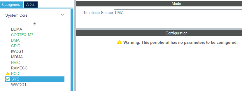
由于使用freertos组件,为了避免警告,系统基础时钟源需要更换为定时器,这里更换为定时器7。
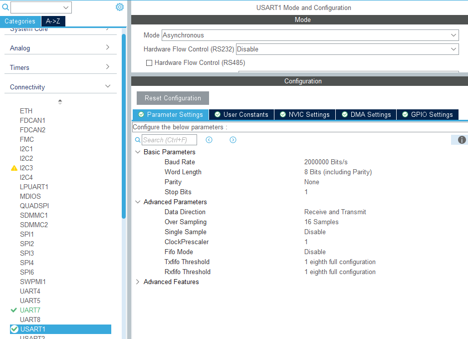
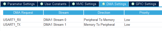
由于microros需要进行大量数据传输,所以修改波特率为2Mbps,并且打开TX和RX的DMA通道。
由于串口1用于microros通讯,那么打印调试信息就修改为串口7。设置波特率为115200,8位数据,无奇偶校验,1位停止。
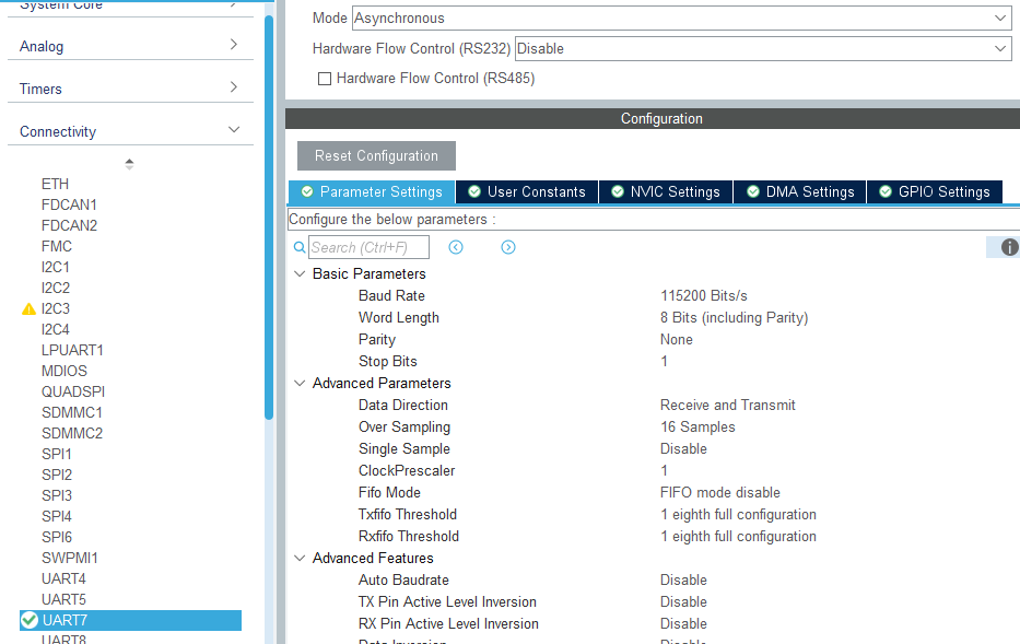
为了方便查看,后续microros例程的调试串口都重定义为串口7。
xxxxxxxxxxint _write(int file, char*p, int len){HAL_UART_Transmit(&huart7, (uint8_t *)p, len, 0xFF);return len;}
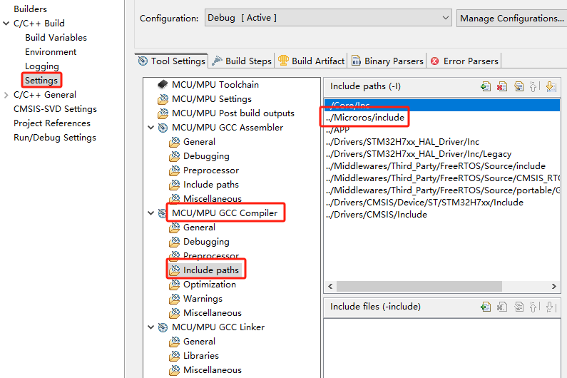
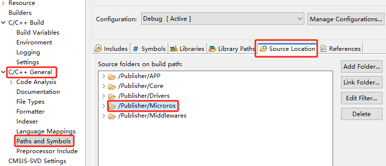
右键打开工程属性,以此点击【Settings】->【MCU/MPU GCC Compiler】->【include paths】增加microros的include目录路径,然后点击【Apply】应用生效。
添加microros文件夹为工程源码路径。
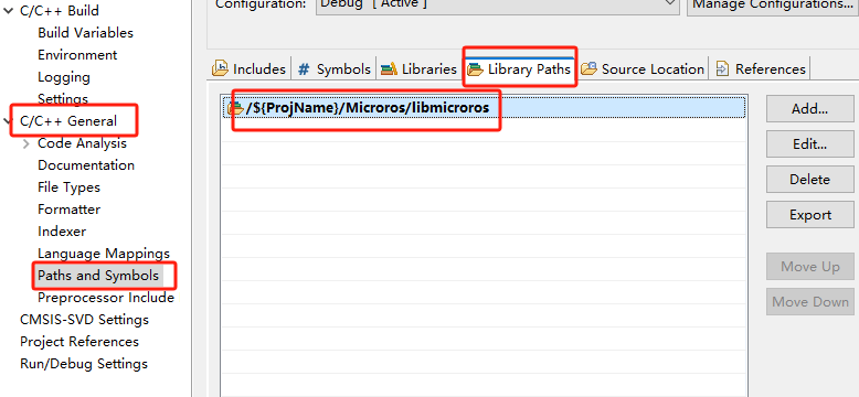
导入microros库路径
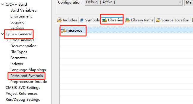
链接microros库文件到工程。注意名称要和libmicroros.a静态库文件名去掉前缀和后缀的名称(microros)保持一致。
初始化microROS的配置,其中ros2_domain_id默认为30,与出厂镜像配置一致,如果ROS2环境的DOMAINID改为其他值,ros2_domain_id变量也要改到相同值才可以正常通讯。
xxxxxxxxxxallocator = rcl_get_default_allocator();rcl_init_options_t init_options = rcl_get_zero_initialized_init_options();RCCHECK(rcl_init_options_init(&init_options, allocator));RCCHECK(rcl_init_options_set_domain_id(&init_options, ros2_domain_id));rmw_init_options_t *rmw_options = rcl_init_options_get_rmw_init_options(&init_options);
设置microros通讯串口,指定为串口1。
xxxxxxxxxxint32_t set_microros_serial_transports_with_options(rmw_init_options_t * rmw_options){int32_t ret = 0;ret = rmw_uros_options_set_custom_transport(true,(void *) &huart1,cubemx_transport_open,cubemx_transport_close,cubemx_transport_write,cubemx_transport_read,rmw_options);return ret;}
设置microros系统申请内存的方法。
xxxxxxxxxxint set_microros_freeRTOS_allocator(void){rcl_allocator_t freeRTOS_allocator = rcutils_get_zero_initialized_allocator();freeRTOS_allocator.allocate = microros_allocate;freeRTOS_allocator.deallocate = microros_deallocate;freeRTOS_allocator.reallocate = microros_reallocate;freeRTOS_allocator.zero_allocate = microros_zero_allocate;if (!rcutils_set_default_allocator(&freeRTOS_allocator)) {printf("Error on default allocators (line %d)\n", __LINE__);return -1;}return 0;}
尝试连接代理,连接成功才进入下一步,如果连接代理不成功则一直处于连接状态。此时需要在控制板上开启代理脚本才可以连接上。
xxxxxxxxxxwhile (1){osDelay(500);state = rclc_support_init_with_options(&support, 0, NULL, &init_options, &allocator);if (state == RCL_RET_OK) break;printf("Reconnecting agent...\n");}
连接代理完成后,创建节点"YB_Example_Node",其中ros2_namespace默认为空,表示节点的命名空间。
xprintf("Start YB_Example_Node\n");node = rcl_get_zero_initialized_node();RCCHECK(rclc_node_init_default(&node, "YB_Example_Node", (char*)ros2_namespace, &support));
创建发布者"int32_subscriber",需要指定发布者的信息为std_msgs/msg/Int32类型。
xxxxxxxxxxRCCHECK(rclc_subscription_init_default(&subscriber,&node,ROSIDL_GET_MSG_TYPE_SUPPORT(std_msgs, msg, Int32),"int32_subscriber"));
创建执行者,其中executor_count参数为执行者控制的数量,要大于或等于添加到执行者的订阅者和发布者数量之和。
xxxxxxxxxxprintf("executor_count:%d\n", executor_count);executor = rclc_executor_get_zero_initialized_executor();RCCHECK(rclc_executor_init(&executor, &support.context, executor_count, &allocator));
添加发布者的定时器到执行者,如果有数据到达,则调用订阅者回调函数。
xxxxxxxxxxRCCHECK(rclc_executor_add_subscription(&executor,&subscriber,&msg,&subscriber_callback,ON_NEW_DATA));
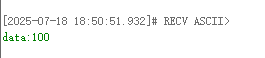
如果接收到数据,则在回调函数中打印出来。
xxxxxxxxxxvoid subscriber_callback(const void *msgin){const std_msgs__msg__Int32 * msg = (const std_msgs__msg__Int32 *)msgin;int32_t msg_data = msg->data;printf("data:%ld\n", msg_data);}
节点和话题处理完毕,电量LED_MCU指示灯。在循环中调用rclc_executor_spin_some来让microros正常工作起来。
xxxxxxxxxxLED_ROS_ON();uint32_t lastWakeTime = xTaskGetTickCount();while (ros_error < 3){rclc_executor_spin_some(&executor, RCL_MS_TO_NS(ROS2_SPIN_TIMEOUT_MS));if (ping_microros_agent() != RMW_RET_OK) break;vTaskDelayUntil(&lastWakeTime, 10);// vTaskDelay(pdMS_TO_TICKS(100));}
ping_microros_agent函数是检查代理是否保持连接,如果连接断开则结束循环。
xxxxxxxxxxint32_t ping_microros_agent(void){static int ping_count = 0;ping_count++;if(ping_count > 100){ping_count = 0;return rmw_uros_ping_agent(100, 1);}return RMW_RET_OK;}
如果代理断开或者话题异常,系统会自动重启单片机。
xxxxxxxxxxprintf("ROS Task End\n");printf("Restart System!!!\n");vTaskDelay(pdMS_TO_TICKS(10));HAL_NVIC_SystemReset();
四、编译下载烧录固件
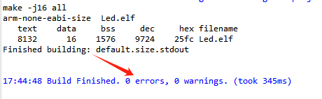
在STM32CUBEIDE上的文件管理界面选中要编译的项目,点击工具栏上的编译按钮即可开始编译。
如果没有错误或者警告,则提示编译完成。
由于microros代理使用的Type-C通讯串口与烧录串口复用,建议使用STlink工具烧录固件。
如果是使用串口烧录,需要Type-C数据线先插入电脑USB口,进入串口下载模式,烧录固件后,再插回主控板的USB口。
五、实验效果
MCU_LED灯每隔200毫秒闪烁一次。
如果主控板终端没有打开代理,请输入以下命令开启代理,如果代理已经启动,请关闭代理后重新执行命令开启代理。
xxxxxxxxxxsh ~/start_agent.sh
连接成功后创建一个节点和一个订阅者。
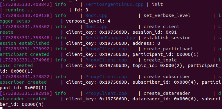
此时可以在虚拟机/电脑另开一个终端,查看/YB_Example_Node节点。
xxxxxxxxxxros2 node listros2 node info /YB_Example_Node
向/int32_subscriber话题发送数据
xxxxxxxxxxros2 topic pub --once /int32_subscriber std_msgs/msg/Int32 "data: 100"
打开串口助手,查看串口7的调试信息,可以看到打印接收到的数据。